DETA Wall Switches
Picked up one of these DETA Smart Double Gang Light Switches from Bunnings today. I had seen they were compatible with Tasmota and was keen to give them a try along with the Brilliant Wall Switch I also posted about recently.
Here are some pictures to get started.
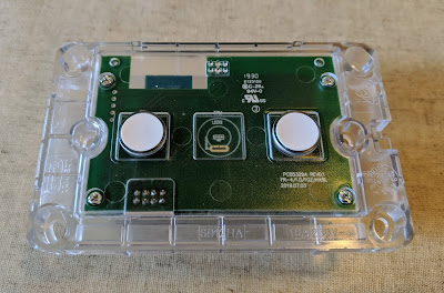
Here is the front of the low-voltage board.
The low-voltage board was pretty easy to get to, with a set of 8 header pins connecting it to the high-voltage board. There are also a set of 5 header holes on the board.
I did a quick continuity check and identified that the upper-most hole as VCC, and the lower hole as GND. I then powered it up with 3.3V and flashed Tasmota onto it using Tuya-convert.
To put the device in pairing mode, it was necessary to press one of the buttons for at least 5 seconds. The LED on the front of the low-voltage panel then starts flashing.
I configured it as per the template here.
Now I just need to get an electrician around to install it.
Here are some pictures to get started.
After removing the front panel, there is another clear plastic panel to be removed before you can get to the boards.
Here is the front of the low-voltage board.
And the high-voltage board
The low-voltage board was pretty easy to get to, with a set of 8 header pins connecting it to the high-voltage board. There are also a set of 5 header holes on the board.
I did a quick continuity check and identified that the upper-most hole as VCC, and the lower hole as GND. I then powered it up with 3.3V and flashed Tasmota onto it using Tuya-convert.
To put the device in pairing mode, it was necessary to press one of the buttons for at least 5 seconds. The LED on the front of the low-voltage panel then starts flashing.
I configured it as per the template here.
Now I just need to get an electrician around to install it.


I wonder if a third capacitive touch switch can be hacked in the centre position?
ReplyDeletePossibly, although I haven't tested it. It looks like the LED might be missing from the centre button.
DeletePresumably the markings and traces on the PCB mean they are planning to release a 3-gang version at some point.
I now have a couple of these. Try to show my architect what can be done. I suspect that the centre position is for the single gang version. When I get a chance I'll trace it out. By the size of the relay board, I doubt they are going to have 3 or 4 gang version. I ordered a brilliant 2-gang and dimmer for trial. There pricing is high but we have little choice..
DeleteI've done basically the same thing; trialled a DETA and Brilliant Wall Switch. At this stage I prefer the ergonomics and aesthetics of the Brilliant, but think the DETA will be more flexible as it doesn't rely on the secondary MCU like the Brilliant. I wrote something quickly on that here a couple of days ago.
DeleteApologies for the basic question! I cant fathom how to disassemble the switch! I've removed the four screws but then it just seems like a hunk of plastic. Any tips? Thanks . :)
DeleteDo you mean the plastic plate that includes the buttons? I think I just levered it out from the side. Use a butter knife, or a small screwdriver.
DeleteHi there, thanks so much for the guide. I have a 4-gang switch. Would, my board looks different to yours (suspect a newer batch?).
DeleteI'm having trouble confirming which are the RST and IO0 pins..
Any chance I could send you an image if you could spare a few minutes?