Posts

Showing posts from October, 2019

DETA Wall Switches

Image
Picked up one of these DETA Smart Double Gang Light Switches  from Bunnings today. I had seen they were compatible with Tasmota  and was keen to give them a try along with the Brilliant Wall Switch I also posted about recently . Here are some pictures to get started. After removing the front panel, there is another clear plastic panel to be removed before you can get to the boards. Here is the front of the low-voltage board. And the high-voltage board The low-voltage board was pretty easy to get to, with a set of 8 header pins connecting it to the high-voltage board. There are also a set of 5 header holes on the board.  I did a quick continuity check and identified that the upper-most hole as VCC, and the lower hole as GND. I then powered it up with 3.3V and flashed Tasmota onto it using Tuya-convert .  To put the device in pairing mode, it was necessary to press one of the buttons for at least 5 seconds. The LED on the front of the low-vol

BH1750 illuminance sensor

Image
A new BH1750 illuminance sensor arrived today. I connected it up to the breadboard with a Wemos D1 running Tasmota, and started and started logging data in Home Assistant. Here is some sample data.

Brilliant Smart Elite Glass Wall Switches Update

Following from my earlier post , I've now been able to configure the Brilliant Wall Switch correctly, thanks to this very helpful post over on the Home Assistant forums. Firstly, the current stable version of Tasmota was 6.6.0, and it was necessary to flash with a newer version which could be found here . I used 6.6.0.20. Then, the device could be configured using the following commands. Module 54 Backlog TuyaMCU 31,103; TuyaMCU 32, 102; TuyaMCU 33, 104; TuyaMCU 11,1; TuyaMCU 12,2 Now I just need to get an electrician to install it...

Comparison between temperature and humidity sensor types

Image
I've been running a Wemos D1 mini in a Frankenstein-like configuration over the past few weeks, with the aim of testing a few different temperature and humidity sensors. I've been trialling the following sensor types: DHT22 DHT11 BME280 SHT30 The breadboard with the sensors looks like this: You can see some graphs of a recent sample of readings from Grafana here: I'm actually a bit disappointed with how much variation there is between these sensors. Overall, I'm more confident in the readings from the DHT22 sensors, based on comparisons with some other temperature sensors I have in the house. The BME280 and SHT30 don't appear to be as accurate as I had hoped. The DHT11 is doing a reasonable job at the temperature readings, but the humidity is probably over-reading.

Update to smart plug rules for controlling bathroom fans manually

Today I made some changes to the rules that let the smart plugs running tasmota in the bathrooms turn on the fans. With these rules a short press turns on the fan, and a long press turns on the switch. Rule1 on switch1#state=3 do Power 2 endon Rule2 on switch1#state=2 do publish cmnd/sw_bri_03/POWER 2 endon Rule1 1 Rule2 1

Brilliant WiFi A60 globes RGB+W (20741)

Image
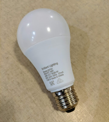
I picked up a 3-pack of these Brilliant WiFi A60 RGB+W E27 globes from Aldi recently (Model Number 20741), with the intention of flashing them with Tasmota  and doing some experimentation in Home Assistant . Firstly, some photos of the bulb and box. I was able to easily flash these with Tasmota easily using tuya-convert , and fortunately there was a template available in the repository , meaning they were also easy to configure.  These globes are controlled via four separate PWM signals for the red, green, blue and white leds. There were also very good instructions on the Tasmota wiki for configuring the globes in Home Assistant.

Brilliant Smart Elite Glass Wall Switches

Image
I purchased one of these Brilliant Smart Elite Wall Switches  which arrived today.  I quickly pulled off the front glass panel and could see the upper surface of the low voltage board.  Fortunately the low voltage board was easily removable, revealing the high-voltage board beneath. The low voltage board  containing the ESP8266 chip on the underside is below. T here were a set of header pins which extended into the mains voltage part that I hoped would offer an easy solution for flashing.   The ESP8266 in this case is on an TYW3ES module which I think is commonly used in Tuya gear. Looking at the TYW3ES data sheet  I was able to identify the pins on the module.  I then did some continuity checks with a multimeter and was able to identify the VCC and GND pins on the header, but unfortunately not the TX or RX pins. I connected the VCC and GND pins to a 3.3V power supply using dupont cables, and the board came to life. Note that