Posts

Featured post

Ender 3 3D Printer

Image
I've previously experimented with trying to find  suitable off-the-shelf enclosures  to house my various controllers and sensors, and had come to the conclusion that the ideal scenario would be to build custom enclosures using a three-dimensional (3D) printer. In last year's Black Friday sales, I was amazed to come across one of the most common 3D printers, the Creality Ender 3 , and find out how cheap they were . Further, even the filament is reasonably priced . So, after a few months of deliberation, I finally took the plunge, and purchased an Ender 3. You can see a photo of the constructed printer here.

Heatsink case for Raspberry Pi 4

Image
Last year I acquired a Raspberry Pi 4  for running Home Assistant and some of my other home automation tasks. I bought the stock case to go with it, and unfortunately since I've had it, it has been running really hot, at times reach as high as 80 degrees. This is a well acknowledged issue , which had improved slightly with some firmware updates in recent months, but regardless I was a bit worried it was going to diminish the lifespan of the Pi 4. So, I went looking for better cases, and came across a number of fanless heatsink cases, which seemed like a good solution as I'd already had some good experience with fanless heatsink cases for PCs. Anyway, I came across this heatsink case from Little Bird Electronics , from where I also purchased my Pi 4 , and decided to give it a go. You can see an image of the case below, so you know where this is heading.

Smart Irrigation Controller with Tasmota and Home Assistant

Image
I've recently been working on a smart, wifi-enabled irrigation or watering controller for my garden, and have finally got it up and running. I'll start with a picture of the finished product, so you know where this is heading. I had a few ideas for how to achieve this, and over the last few months I've been examining different options, and recently took the plunge and purchased some hardware. I've been doing a number of projects with ESP8266 based hardware, Tasmota firmware, and Home Assistant and so it was inevitable any solution I put in place would feature those elements.

Brilliant Smart Ceiling Fan Remote in Home Assistant

Image
A few months ago I purchased a Brilliant Smart Ceiling Fan Remote or Controller , with the intention of flashing Tasmota on it, and setting it up in Home Assistant . I needed to replace a ceiling fan in our lounge room, and so I also bought a Brilliant Tempest II ceiling fan , which I understood should be compatible with the fan controller. You can see a few photos below, but unfortunately I forgot to take any before I had disassembled the parts, so you'll need to check out the BrilliantSmart product page to see photos before disassembly. Here is the box... And the control panel with the cover removed... And the controller, also with the cover removed... Fortunately, thanks to some very   helpful   posts  and investigative work from sparkydave , thecubical and exxalmate  and posted on the  Australia - Electrically Certified Hardware thread  on the Home Assistant forums , I knew that this was a Tuya based device, with a secondary microcontroller unit (MCU). Fort

Brilliant WiFi A60 globes RGB+W (20699)

Image
After having some recent success with the Brilliant RGB+W 20741 E27 globes , I decided to purchase the B22 version of (what I thought) was the same globe, the Brilliant WiFi A60 RGB+W 20699 B22 globe . You can see some images of the globe and box here. I followed the same process as with the 20741, flashing Tasmota using  tuya-convert , and attempting to use the  template for the 20741 in the repository . The 20741 template uses the following pin assignment: GPIO4 - PWM1 - red GPIO12 -  PWM2 -   green GPIO14 -  PWM3 -   blue GPIO5 -  PWM4 -   warm white To test the globe, I then tried cycling through the following commands in the Tasmota console to light each led: red: Color1 1 green: Color1 2 blue: Color1 3 white: White 100 After this test, the only response I saw from the globe was the white led was lit when I tried to set the globe to a green colour. This told me the 20741 template wasn't correct for this globe, but also gave me a hint that the white

Controlling Samsung Air Conditioner from Home Assistant

Image
I've gradually been connecting as many devices as I can using Home Assistant. One of the things that has been on my list is our WiFi connected Samsung Air Conditioner. It is a Samsung model AR24FSSSBWKN sold in Australia in around 2015. We have made use of being able to control the air conditioner using the Samsung Smart Air Conditioner Android app , but it has always been problematic. It consistently requires a username and password to be entered when using it outside of the home, recently it has stopped working inside the home, and it also requests some (in my view) unnecessary permissions (such as telephone and contacts). So, the idea of being able to control it via Home Assistant is appealing. I'd considered trying to set something up with my Broadlink IR Pro  to control it via IR, but most of the possible solutions seemed a bit clumsy. I became aware of the climate_ip custom component for Home Assistant  created by SebuZet who is active on the Home Assistan

Enclosure for Wemos D1 Mini and environmental sensors

Image
I've been trying for a number of weeks to find a solution to house a Wemos D1 Mini and some environmental sensors. There are lots of good options for 3D printed enclosures , and I read many posts like this , but I could quite find something that I thought would work. Eventually I stumbled across this video , that showed a nice simple looking case available from Bangood . I purchased a couple of different sizes, which you can see in the images below. The smaller is  70x54x27mm , and the larger is  100x80x32mm . I also purchased some of these mini breadboards, as I was hoping to make temporary connections between a Wemos D1 Mini and various sensors just using Dupont cables, so that I could easily change the sensor setup without having to resolder. I've found these breadboards to be very nice for quickly hooking various sensors up to the Wemos D1 Mini, and you can see some examples below. The smaller enclosure size was great for just throwing an ESP

Using a USB mSATA SSD with the Raspberry Pi 4

Image
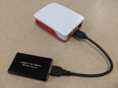
I've recently realised that many people have experienced issues with failure of microSD cards used in a Raspberry Pi, as a result of heavy usage that the cards potentially weren't intended for. I've been using Home Assistant to log reasonably high-frequency data from multiple sensors, and also to save the data using influxdb , and plot it using grafana . I was conscious that this may place increased strain on the microSD card over time, and so wanted to look for an alternative before my microSD card died. I was also interested to find a solution that might give the Pi 4 and Home Assistant a performance boost.  I settled on a 120GB mSata SSD and a small USB 3.0 enclosure which would allow me to connect the mSata SSD to the Raspberry Pi 4. You can see some photos below. After connecting the SSD to the Raspberry Pi 4, I ran some quick speed tests, that suggested the mSata SSD over USB 3.0 was significantly faster than the microSD card. See below. write

DETA Wall Switches

Image
Picked up one of these DETA Smart Double Gang Light Switches  from Bunnings today. I had seen they were compatible with Tasmota  and was keen to give them a try along with the Brilliant Wall Switch I also posted about recently . Here are some pictures to get started. After removing the front panel, there is another clear plastic panel to be removed before you can get to the boards. Here is the front of the low-voltage board. And the high-voltage board The low-voltage board was pretty easy to get to, with a set of 8 header pins connecting it to the high-voltage board. There are also a set of 5 header holes on the board.  I did a quick continuity check and identified that the upper-most hole as VCC, and the lower hole as GND. I then powered it up with 3.3V and flashed Tasmota onto it using Tuya-convert .  To put the device in pairing mode, it was necessary to press one of the buttons for at least 5 seconds. The LED on the front of the low-vol